| Previous - Positioning units with Drag and Drop. | Return to Index. | Next - Changing the colours in your design. |
This chapter covers the various options for viewing your design.
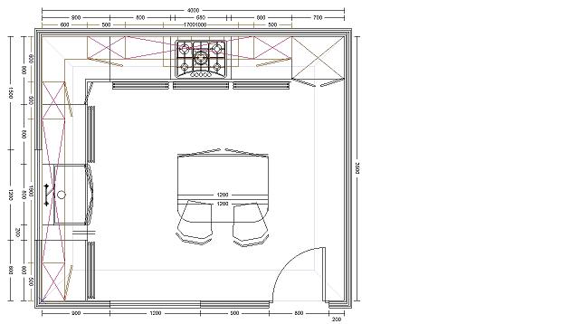
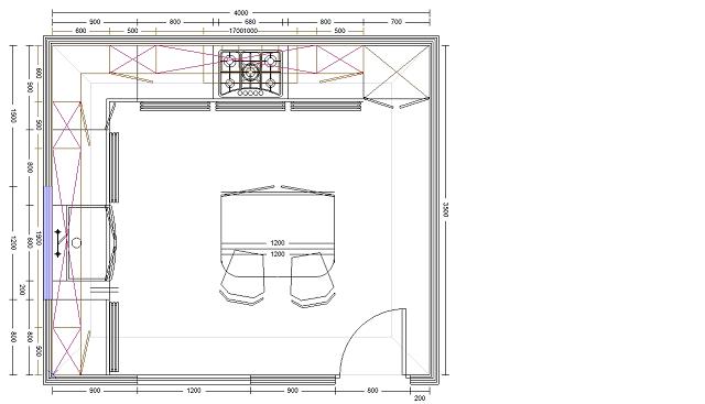
Unless otherwise stated, all the below examples use this plan.
An elevation view will show you everything touching a selected wall run. Units have to be touching the wall to show up in the elevation. If you elevate a wall and units don't show up that you are expecting to see, check that they are locked flush with the wall - See Positioning Units with DND for details on snapping units to the wall.
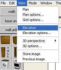
To generate an elevation, first hightlight the wall run in your design you wish to elevate. Left-click on the wall, and it will highlight. click "View" - "Elevation".
Example 1.
The selected wall is hightlighted in blue. Clicking "View" - "Elevation" will generate an elevation of the selected wall.
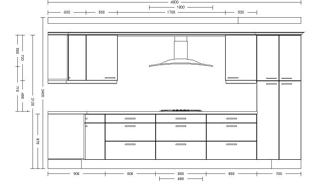
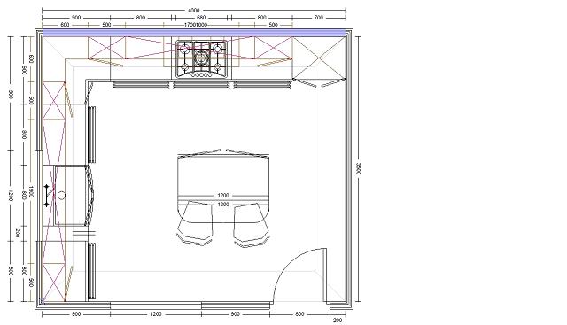
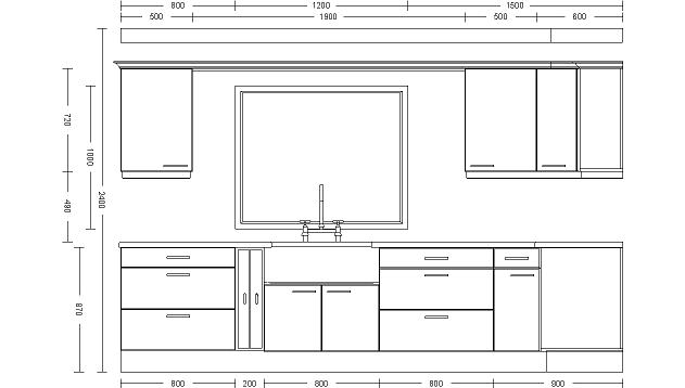
Example 2.
This wall run is made up of a wall, a window and another piece of wall. You can only select one wall item at a time. Selecting any of the items making up this wall run will elevate the entire wall run. In this example only the window is selected (though it could be either of the wall sections).
Example 3. Colour elevations.
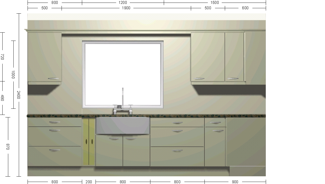
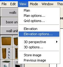
To change from line drawing elevations to colour, click "View" - "Elevation Options".
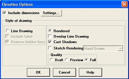
The default setting is "Line Drawing" (see Example 2). Change it to "Rendered". Create the elevation using the same method as covered in examples 1 and 2.
Return to top.
The bird's eye view (BEV) gives you a top-down view of your current design. The view will fit your entire design onto the screen. In order to do it may be necessary to have a gap either side of the image. This gap will be filled with the currently selected sky colour.
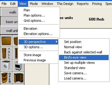
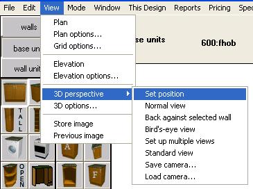
You can generate a BEV at any time by clicking "View" - "3D perspective" - "Bird's eye view".
Example 1. BEV of our example room.
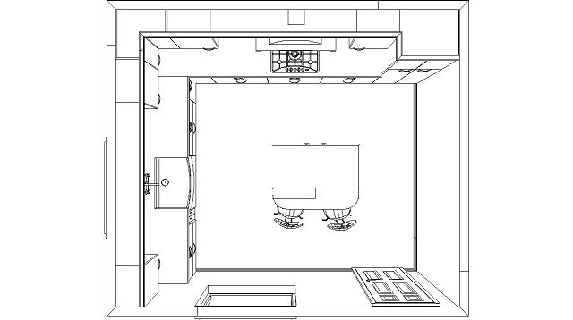
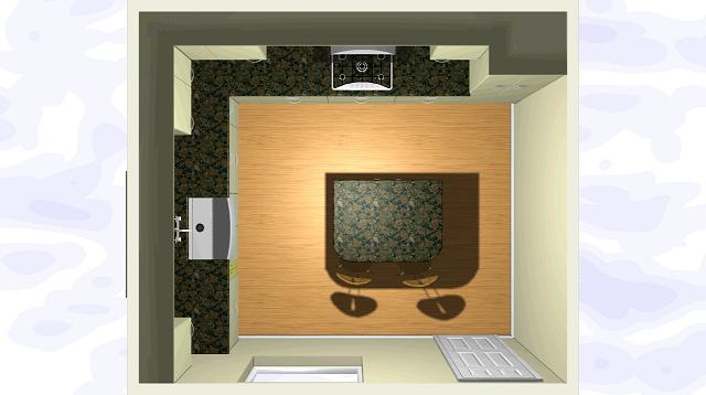
Examples of a BEV in line drawing and colour (note the sky showing either side). See the section below Switching from Line Drawing to Colour views for details on changing between the two.
Return to top.
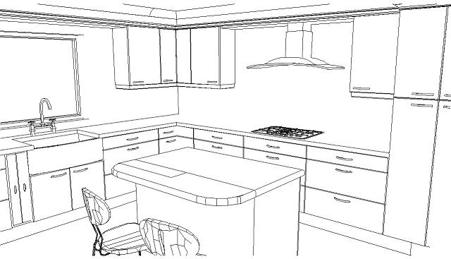
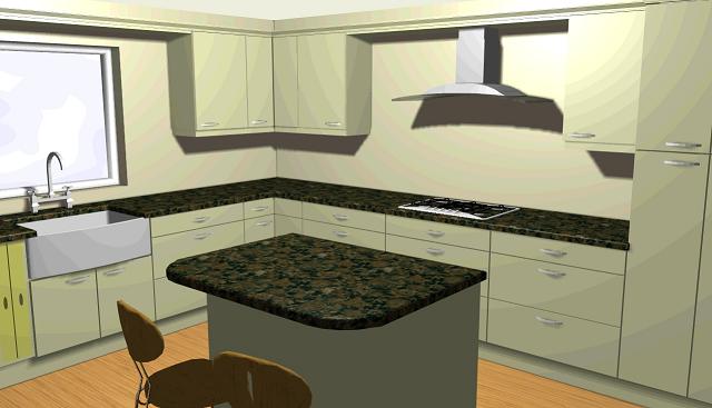
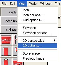
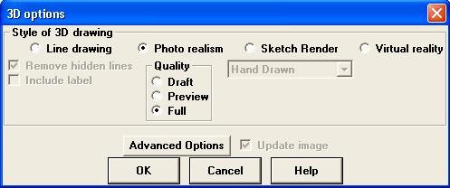
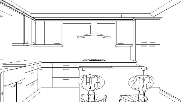
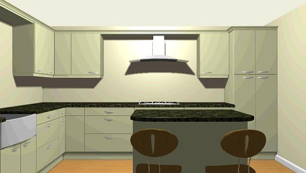
There are two options for creating 3D images in ArtiCAD - Line Drawing (first image) and Photo-realistic Colour (second image). To change between the two options, click "View" - "3D Options".
Selecting either option will mean any views EXCEPT elevation will be created using that option. For details on changing elevations between line and colour modes, see the Elevations section of this chapter.
Details of the "Sketch Render" and "Virtual Reality" options can be found in Appendix 6. VR and Sketch render.
Return to top.
Creates a view facing into the room from the middle of the selected wall run.
To generate this view, first hightlight the wall run in your design you wish to view from. Left-click on the wall, and it will highlight. click "View" - "3D Perspective" - "Back Against Selected Wall".

As with creating an elevation, you can select any part of a wall run. The view will be generated from the center of the entire wall run, not just the selected part.
Example 1.

Return to top.
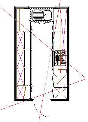
This allows you to position your own camera anywhere within your design.
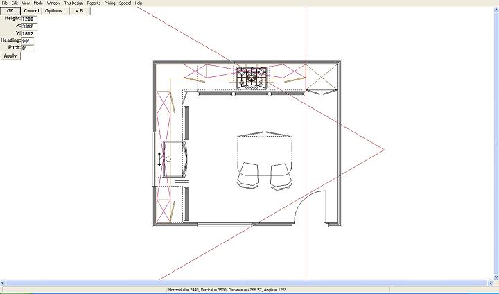
The camera defines which part of your design you wish to view.
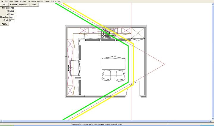
The green line on the above image shows the field of view of the camera. Once you have positioned your camera you will see everything to the left of the green line. Everything behind the yellow line is outside your field of view.
When positioning the camera you should the try and keep the field of view inside the room. If the field of view is outside the room the "gap" will be filled with the current sky colour.
Summary of controls when positioning your camera. Hold down the left-mouse button to perform the action. Single right-click to cycle through the camera options.
| Icon | Action | Keyboard shortcut |
|---|---|---|

|
Move the camera. | Cursor keys - up, down, left, right |

|
Rotate the camera. | "a" rotates anti-clockwise, "c" rotates clockwise. |

|
Resize the camera. | "+" increase camera size, "-" decrease camera size. |

|
Change viewing angle. | "w" widens the angle, "n" makes it narrower. |

|
Position the cut line. | "1" moves the line forward, "2" moves the line back. |
Holding down the "Control"/"Ctrl" key whilst using any of the keyboard controls will decrease the amount the camera attribute changes e.g. holding down "Control" and pressing "a" will rotate the camera in smaller steps than pressing "a" alone. Allows you a finer degree of control.
Pressing the "Tab" key will reset the camera back to the defaults.
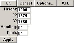
Once you have the camera in the correct position, click "OK" in the top-left corner of the screen to generate the image.
Clicking the "Cancel" button in the top-left corner will return you to the design screen.
Clicking the "Options" button is the same as clicking "View" - "3D Options".
Clicking the "VR" button will start a Virtual Reality view of your design, based on the current camera position. See chapter X - VR.
Right-click until the "Movement" icon appears next to the mouse. Hold down the left mouse button anywhere on the camera and drag it into position.
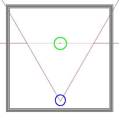
The camera rotates about the center of the front of the camera (shown in green, above).
When using the mouse it is best to "hold" the camera by the point (shown in blue, above) and drag around the point of rotation. If your mouse pointer crosses the front of the camera whilst rotating it will "snap" round to face in the opposite direction.
Right-click the mouse until the "Resize" icon appears next to the mouse. Hold down the left mouse button anywhere on the camera and drag. Move away from the front of the camera to englarge, towards to shrink.
Used when working with smaller designs as the default size of the camera may be physically too large to fit inside the design.
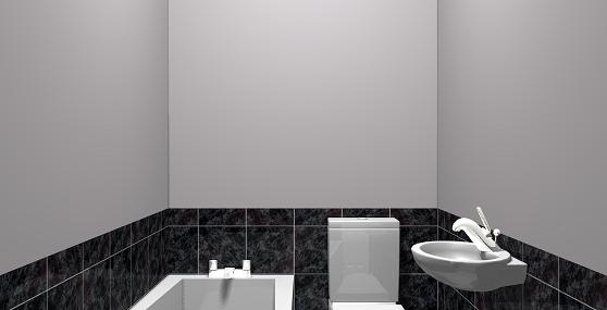
Using the below bathroom design as an example.
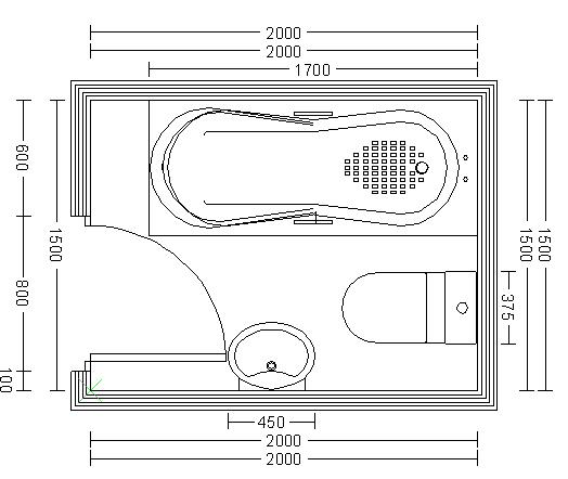
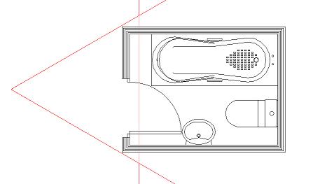
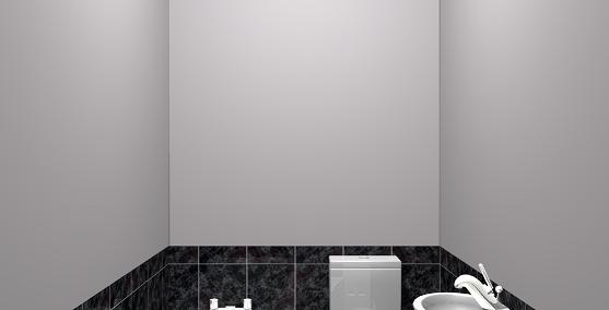
The default camera size is too large for this design. You can see the sky either side of the image.
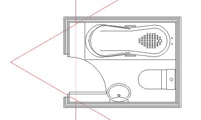
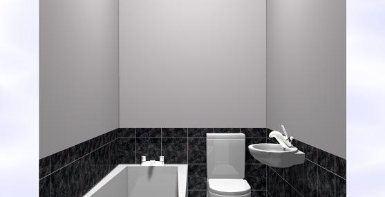
With the size of the camera reduced, the image only shows the interior of the design.
Right-click the mouse until the "Viewing angle" icon appears next to the mouse. Hold down the left mouse button anywhere on the camera and drag. Move away from the front of the camera to reduce the viewing angle, towards to increase.
Increasing the viewing angle allows more of the design to be seen in a single image. However, it has the side effect of creating a "fish eye" effect. Used when working with smaller/narrow designs.
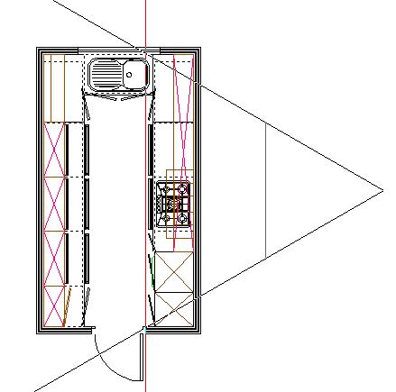
Using this plan as an example:
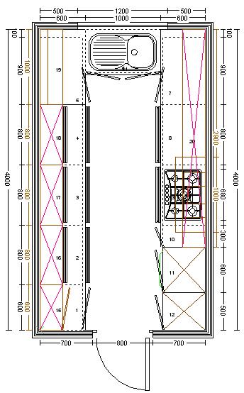
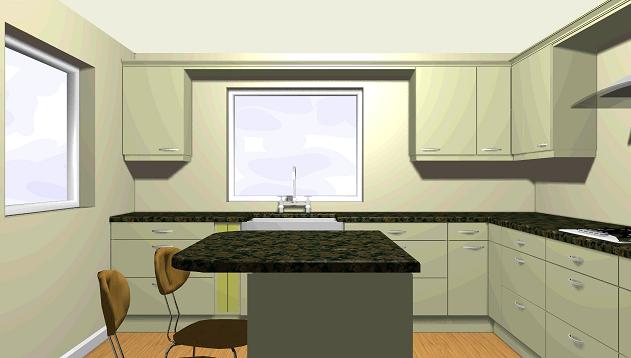
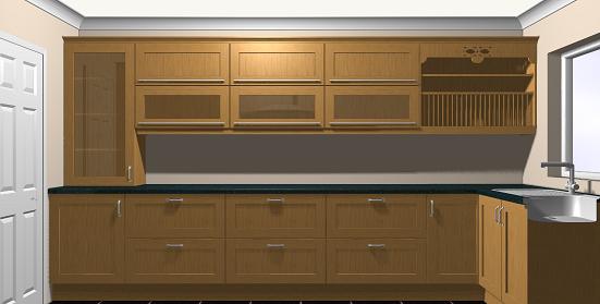
Using the camera with it's default viewing angle gives the following image:
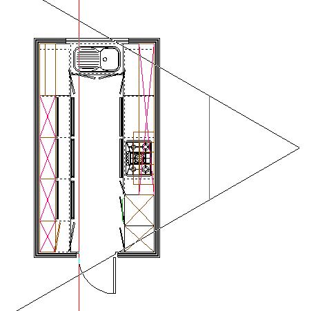
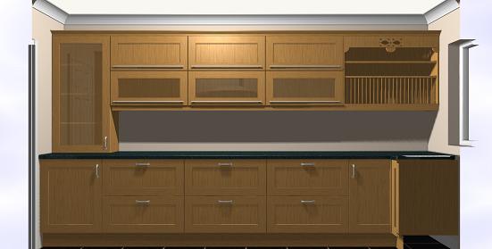
Same camera position, but with the width increased to maximum:
Right-click the mouse until the "Cut line" icon appears next to the mouse. Hold down the left mouse button in front of the camera and drag.
The cut line allows you to remove items from a view that may be blocking your line of sight. Used when working with smaller/narrow designs. Everything in front of the camera but behind the cut line will be removed from the view.
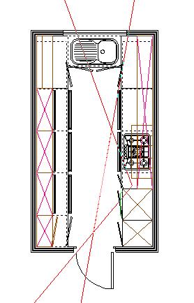
Using this plan as an example:
Due to the layout of this design, it is difficult to get a view of the units running down either of the long walls. The camera can be positioned outside the room so that the entire wall is visible, however the units on the opposite wall get in the way.
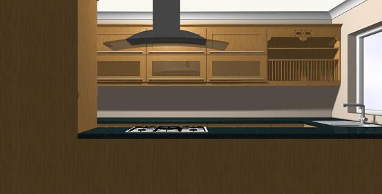
By moving the cut line forward you can remove the units that are in the way.
Notice that the cut line slices through all units e.g. the sink to the right of the image.
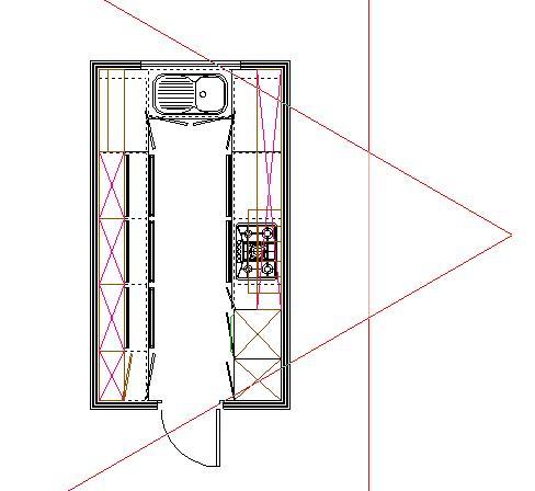
WARNING: Do not move the cut line too far forward:
In the above example the cut line has been moved too far forward so that the camera extends to either side of the plan. This results in a section of sky either side of the image.
The current position and heading of the camera are shown in the top-left corner of the screen. The height is the height of the camera off the floor. The pitch is the angle the camera is "looking" relative to the horizontal. Increasing the pitch looks "up" towards the ceiling (a pitch of 90 would be looking straight up). A negative putch looks "down" towards the floor (a pitch of -90 would be looking straight down). The pitch can be any value between -90 and 90.
Using the below bathroom plan as an example.
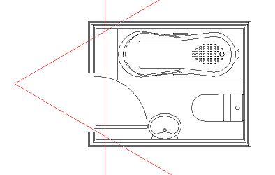
Note - the camera size has been reduced so it fits inside the design.
With the camera height increased to 1400.
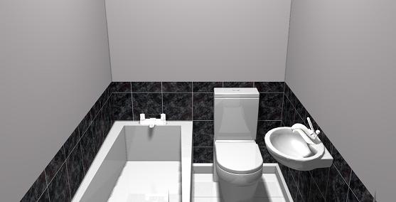
And with the pitch set to -20.
Return to top.
In order to use an image on your Page Layout, you first need to store it. For details of creating a page layout see Creating page layouts.
NOTE - a STORED image only exists in the current ArtiCAD session. These images will be lost when you exit UNLESS they are saved.
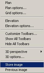
Click "View" - "Store Image".
A dialog box appears to confirm the image has been stored. Click "OK" to remove it.
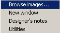
To see the images you have stored, click "Window" - "Browse Images".
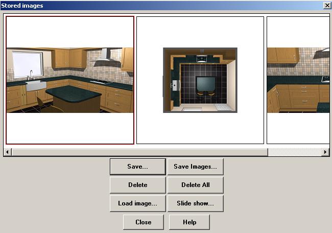
The stored images are displayed in a list from left-to-right. The currently selected image has a red outline.
Return to top.
The following applies to all room systems.
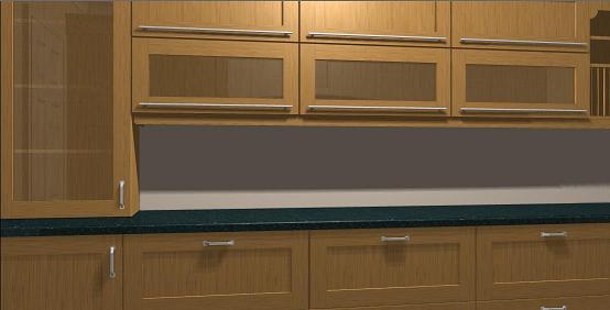
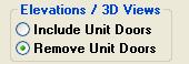
To see the interior of your units, click "This Design" - "Room Settings" and change "Elevation / 3D Views" to "Remove Unit Doors".
NOTE - this setting is saved with your design. If "Remove Unit Doors" is selected when you save your design they will still be removed when you next load the design.
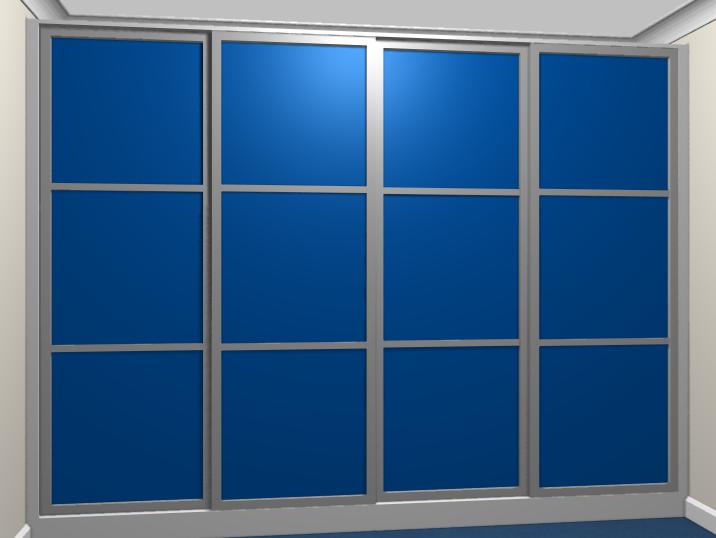
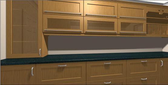
With "Include Unit Doors" selected.
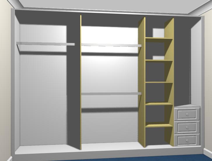
With "Remove Unit Doors" selected.
Return to top.